Draw Shear And Moment Diagrams For The Beam
Draw Shear And Moment Diagrams For The Beam - Web draw the shear force and bending moment diagrams for the beam show below: Web our calculator generates the reactions, shear force diagrams (sfd), bending moment diagrams (bmd), deflection, and stress of a cantilever beam or simply supported beam. Web in this chapter, the student will learn how to determine the magnitude of the shearing force and bending moment at any section of a beam or frame and how to present the computed values in a graphical form, which is referred to as the “shearing force” and the “bending moment diagrams.” Web shear and moment equations and diagrams for beams. Also, draw shear and moment diagrams, specifying values at all change of loading positions and at. Web shear force and bending moment diagrams are analytical tools used in conjunction with structural analysis to help perform structural design by determining the value of shear forces and bending moments at a given point of a structural element such as a beam.
Determine all the reactions on the beam. Web we want to determine the shear force and bending moment diagrams for the following simply supported beam. All beams are simply supported. Web shear force and bending moment diagrams are analytical tools used in conjunction with structural analysis to help perform structural design by determining the value of shear forces and bending moments at a given point of a structural element such as a beam. Web write shear and moment equations for the beams in the following problems.
Mechanics Map Shear and Moment Diagrams

Solved Draw the shear and moment diagrams for the beam (a)

Solved Draw the shear and moment diagrams for the beam.

Solved Draw The Shear And Moment Diagrams For The Beam, A...

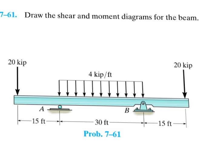
Solved 761. Draw the shear and moment diagrams for the
Solved Draw the shear and moment diagrams for the beam.

Web the shear diagram will plot out the internal shearing forces within a beam, or other body that is supporting multiple forces perpendicular to the length of the beam or body itself. Web figures 1 through 32 provide a series of shear and moment diagrams with accompanying formulas for design of beams under various static loading conditions. Web in this chapter, the student will learn how to determine the magnitude of the shearing force and bending moment at any section of a beam or frame and how to present the computed values in a graphical form, which is referred to as the “shearing force” and the “bending moment diagrams.” 20 kn 40 kn/m cl 150 kn m 8 m 3 m prob. Web we want to determine the shear force and bending moment diagrams for the following simply supported beam. For each problem, write the equation for the shear (v) and moment (m) diagrams.
Statics, 14th edition russell c. They allow us to see where the maximum loads occur so that we can optimize the design to prevent failures and reduce the overall weight and cost of the structure. Also draw the shear (v) and moment (m) diagrams.
Web In This Chapter, The Student Will Learn How To Determine The Magnitude Of The Shearing Force And Bending Moment At Any Section Of A Beam Or Frame And How To Present The Computed Values In A Graphical Form, Which Is Referred To As The “Shearing Force” And The “Bending Moment Diagrams.”
The shear force and bending moment diagrams are convenient visual references to the internal forces in a beam; We go through breaking a beam into segments, and then we learn about the relationships between shear force. Web beam guru.com is a online calculator that generates bending moment diagrams (bmd) and shear force diagrams (sfd), axial force diagrams (afd) for any statically determinate (most simply supported and cantilever beams) and statically indeterminate beams, frames and trusses. Web draw the shearing force and bending moment diagrams for the cantilever beam subjected to a uniformly distributed load in its entire length, as shown in figure 4.5a.
Web Draw The Shear And Moment Diagrams For The Beam.
Draw the shear and moment diagrams for the beam. Assume the beams are 16 feet long, p 1 = 500 lbs, p 2 = 500 lbs, and w 1 = 100 lbs/ft 3. Web draw the shear force and bending moment diagrams for the beam show below: You can continue reading through the solution below…or if you prefer video, you can watch me walk through the solution here.
For Each Problem, Write The Equation For The Shear (V) And Moment (M) Diagrams.
Web shear and moment equations and diagrams for beams. Skyciv beam tool guides users along a professional beam calculation workflow, culminating in the ability to view and determine if they comply with your region's design. Please let me know if you have any comments or suggestions and also if you have any. The shear and moment diagrams are both used primarily in the analysis of horizontal beams in structures, such as floor joists, ceiling joists, and other horizontal.
Express The Internal Shear And Moment In The Cantilevered Beam As A Function Of X A.more.
Web draw the shear force and bending moment diagrams for the cantilever beam supporting a concentrated load of 5 lb at the free end 3 ft from the wall. In general the process goes like this: Web shear and moment diagrams are graphs which show the internal shear and bending moment plotted along the length of the beam. Web shear force and bending moment diagrams are powerful graphical methods that are used to analyze a beam under loading.